


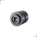
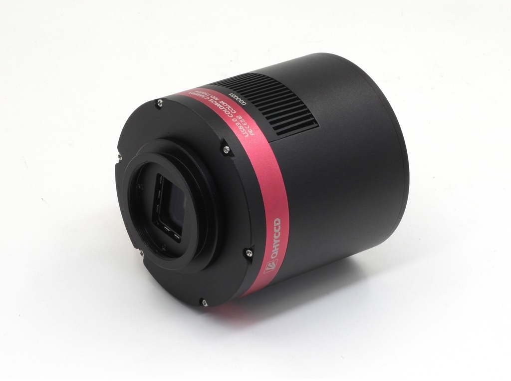
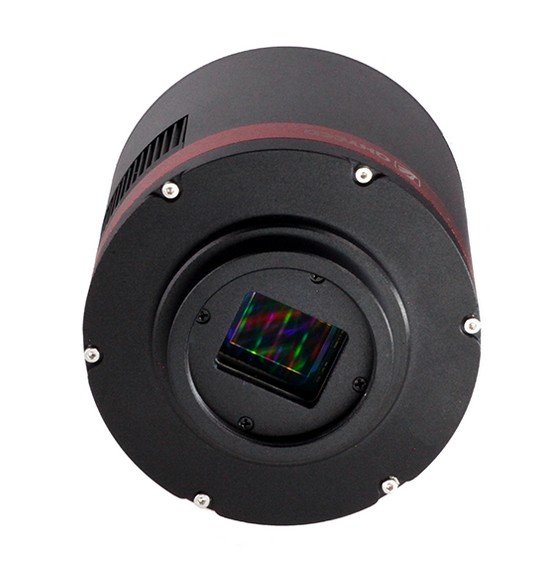

The new QHY294 Pro is a 4/3-inch back-illuminated camera, equipped with Sony IMX294 (Color) and IMX 492 (Mono) sensor. The 294 Pro has 11.7 MP at 4.63um, 14-bits A/D. The IMX294 and IMX492 chips have 46.8 million 2.315um pixels, which Sony 2×2 bins on-chip to create the sensor’s advertised 11.7 million 4.63um pixel array. The QHY294 Pro series camera is capable of locking and unlocking the on-chip binning to provide two readout modes. The first mode reads the sensor “locked” mode to produce 11.6mp images with 4.63um pixel size and 14 bits per pixel. The second read mode unlocks the binning to produce 46.8mp images with 2.315um pixel size at 12 bits per pixel.
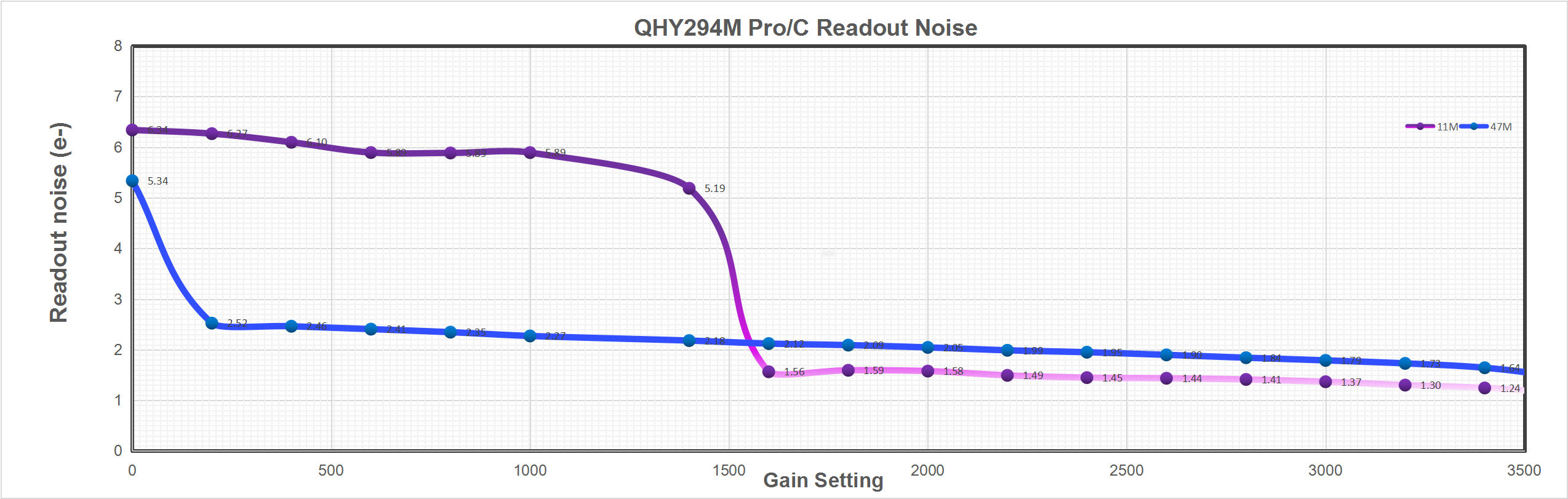
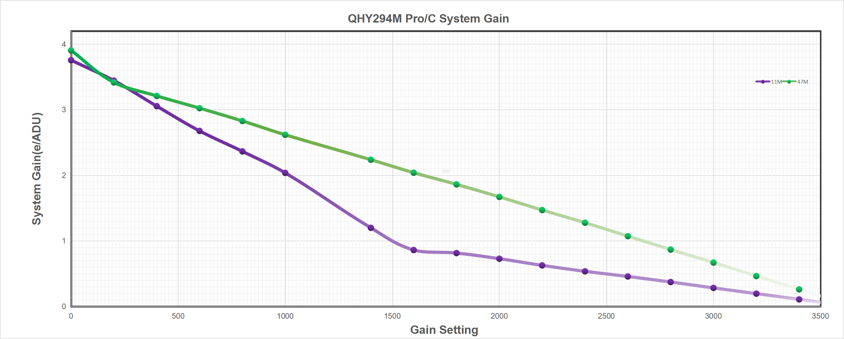
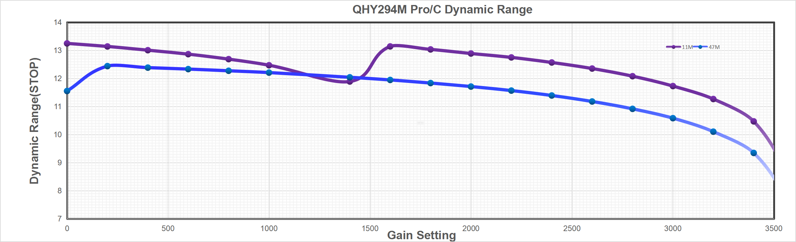
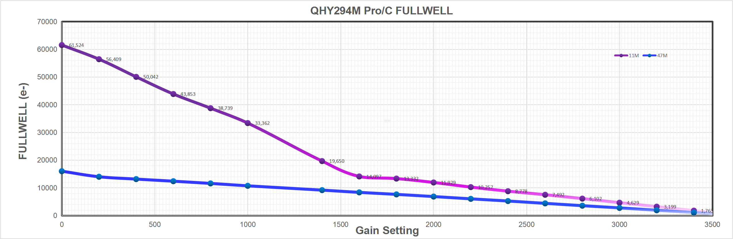
The QHY294 Pro CMOS sensor has a dual gain mode, HGC (high gain) and LGC (Low gain). The QHY294 Pro will switch the two modes automatically when the gain is set to 1600 you will get the benefits of the ultra low read noise (1e- to 1.6e-) of the HGC mode and a full well capacity of about 14.5ke- at the switch point setting.
 BSI
BSI
One benefit of the back-illuminated CMOS structure is improved full well capacity. In a typical front-illuminated sensor, photons from the target entering the photosensitive layer of the sensor must first pass through the metal wiring that is embedded just above the photosensitive layer. The wiring structure reflects some of the photons and reduces the efficiency of the sensor.
In the back- illuminated sensor the light is allowed to enter the photosensitive surface from the reverse side. In this case the sensor’s embedded wiring structure is below the photosensitive layer. As a result, more incoming photons strike the photosensitive layer and more electrons are generated and captured in the pixel well. This ratio of photon to electron production is called quantum efficiency. The higher the quantum efficiency the more efficient the sensor is at converting photons to electrons and hence the more sensitive the sensor is to capturing an image of something dim.
 TRUE RAW Data
In the DSLR implementation there is a RAW image output, but typically it is not completely RAW. Some evidence of noise reduction and hot pixel removal is still visible on close inspection. This can have a negative effect on the image for astronomy such as the “star eater” effect. However, QHY Cameras offer TRUE RAW IMAGE OUTPUT and produces an image comprised of the original signal only, thereby maintaining the maximum flexibility for post-acquisition astronomical image processing programs and other scientific imaging applications.
 Anti-Dew Technology
Based on almost 20-year cooled camera design experience, The QHY cooled camera has implemented the fully dew control solutions. The optic window has built-in dew heater and the chamber is protected from internal humidity condensation. An electric heating board for the chamber window can prevent the formation of dew and the sensor itself is kept dry with our silicon gel tube socket design for control of humidity within the sensor chamber.

Cooling
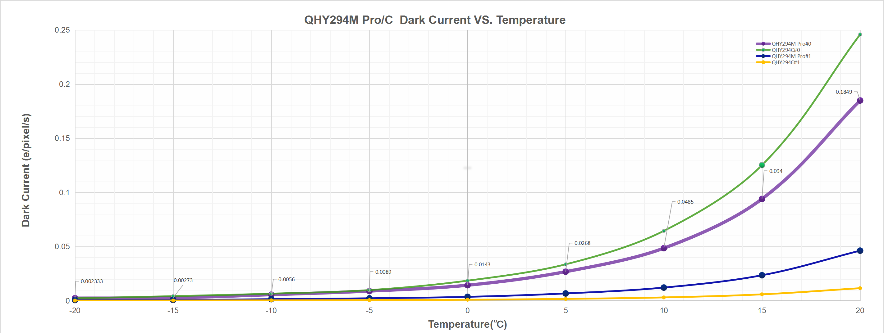
In addition to dual stage TE cooling, QHYCCD implements proprietary technology in hardware to control the dark current noise.
Curves

Centaurus A
By Amit Ashok Kamble, QHY294M Pro
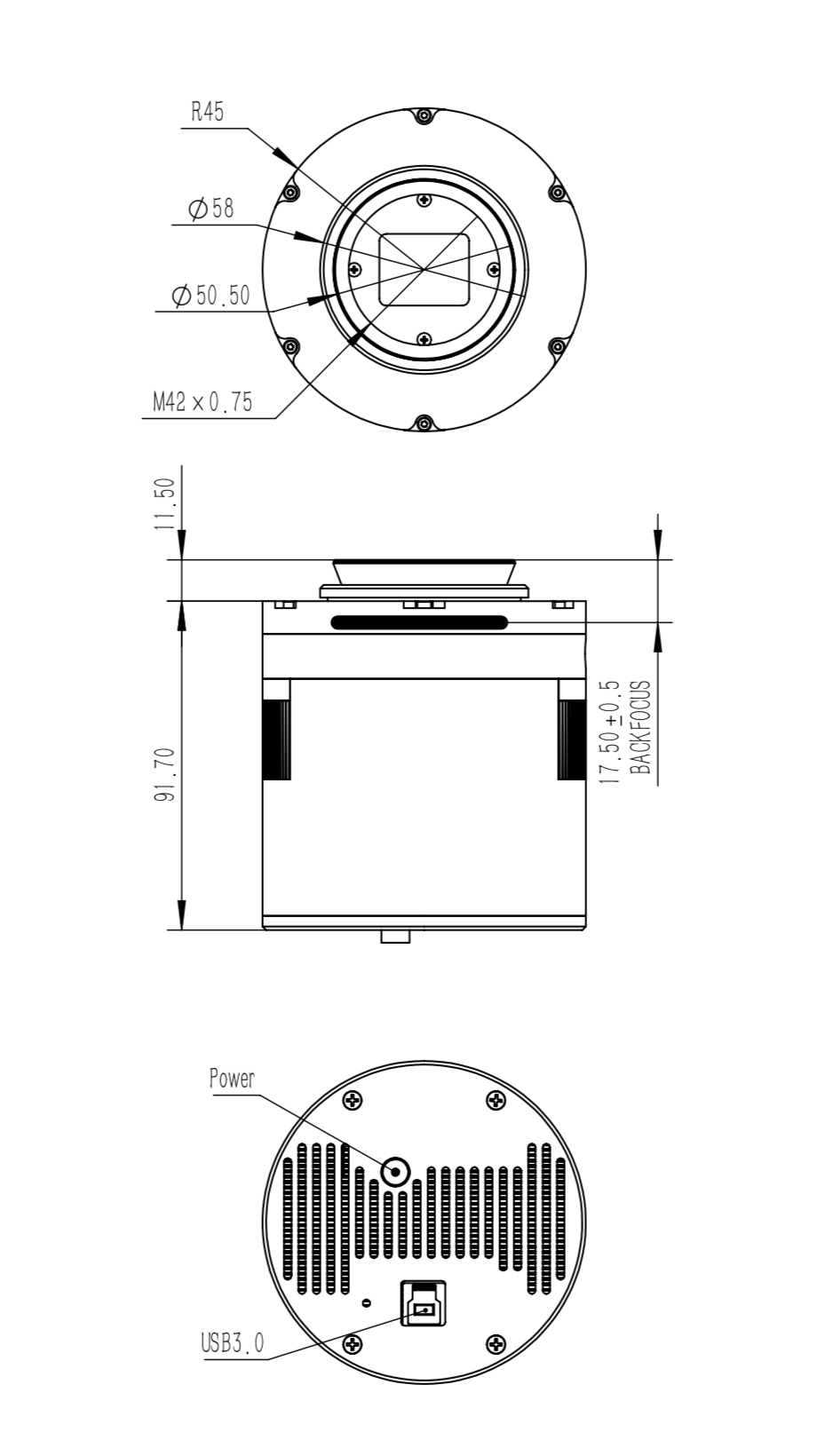
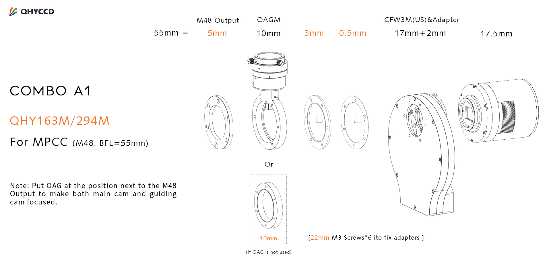
For cameras with a sensor larger than 1-inch and smaller than APS-C (QHY163m/294m) we recommend a combination of CFW3M (US) + OAGM (optional);
| Model | BFL Consumed | Filters Supported |
| QHY163M/294M | 17.5mm | 7 position
36mm unmounted |
| CFW3M-US | 17.5mm | |
| OAGM | 10mm |
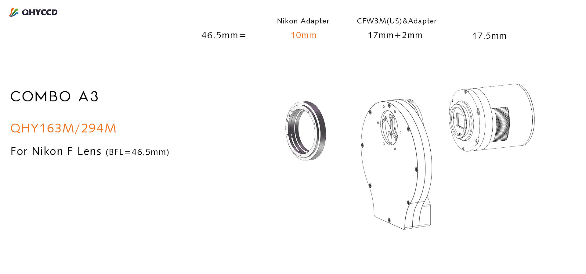
Back Focal Length (BFL), in the commercial camera field, refers to the design distance from the center of the rear lens element to the surface of the sensor. Generally, the lens will only focus correctly at infinity if the camera’s back focal length meets the standard requirements provided by the lens manufacturer. This is also true for many Multi-Purpose Coma Correctors designed to be used on telescopes before the camera.
| Optical system | Back focal length required |
| Typical Multi-Purpose Coma Corrector | 55mm – 57.5mm |
| Canon 35mm lens | 44.1mm |
| Nikon 35mm lens | 46.5mm |
Note:
- If you only own CFW3M-SR whose BFL is 20.5mm rather than 17.5mm, this adapter combination can still be used, just remove the 3mm and 0.5mm adapters.
- If your MPCC requires a BFL different from 55mm, this adjustment can be made by selecting the appropriate spacer between the MPCC and the OAG. For example, an MPCC that requires 57.5mm can be used instead by adding a spacer ring or rings that add 2.5mm of BFL. to the diagram above.
- If you don’t use an OAG, you can use a 10mm spacer adapter in the adapter kits to replace the original position of OAG.
- Put OAG at the position next to the M48 Output to make both main cam and guiding cam focused.
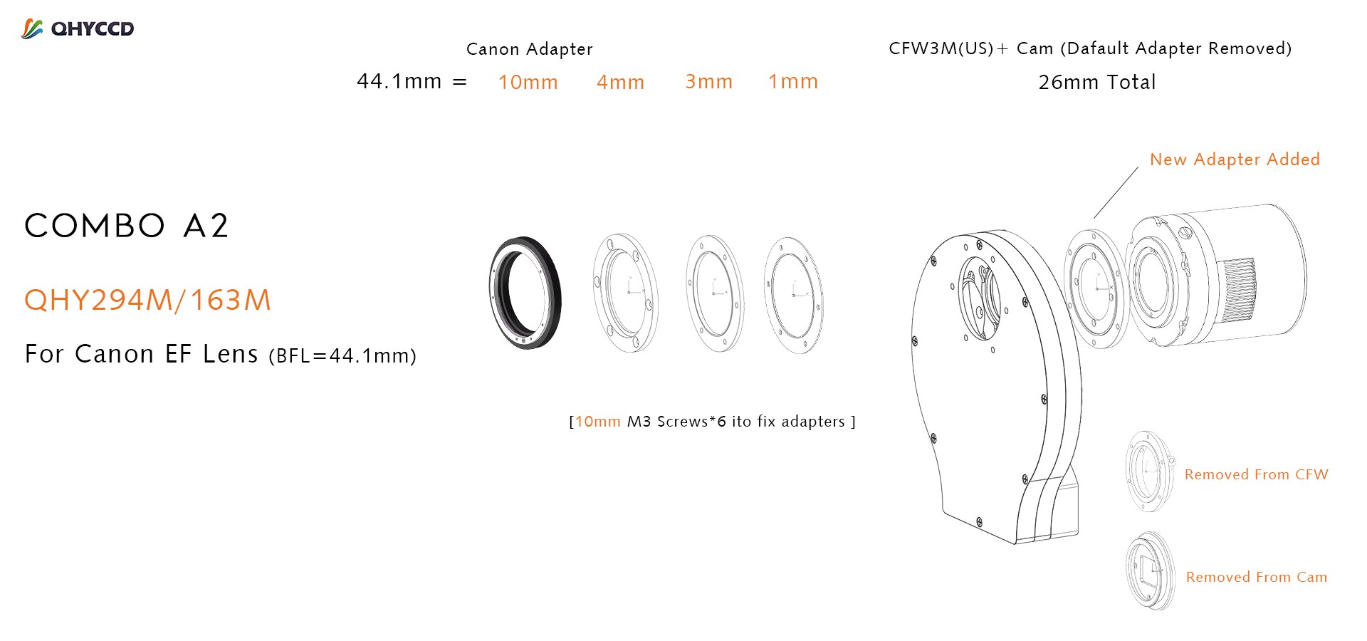
Note: You need to remove the filter wheel and the original connection interface of the camera and replace it with a new adapter.
The camera requires an input voltage between 11V and 13.8V. If the input voltage is too low the camera will stop functioning or it may reboot when the TEC power percent is high, causing a drain on the power. Therefore, please make sure the input voltage arrived to the camera is adequate. 12V is the best but please note that a 12V cable that is very long or a cable with small conductor wire may exhibit enough resistance to cause a voltage drop between the power supply and the camera. The formular is: V(drop) = I * R (cable). It is advised that a very long 12V power cable not be used. It is better to place the 12V AC adapter closer to the camera.
First connect the 12V power supply, then connect the camera to your computer via the USB3.0 cable. Make sure the camera is plugged in before connecting the camera to the computer, otherwise the camera will not be recognized. When you connect the camera for the first time, the system discovers the new device and looks for drivers for it. You can skip the online search step by clicking “Skip obtaining the driver software from Windows Update” and the computer will automatically find the driver locally and install it. If we take the 5IIISeries driver as an example (shown below), after the driver software is successfully installed, you will see QHY5IIISeries_IO in the device manager.
Please note that the input voltage cannot be lower than 11.5v, otherwise the device will be unable to work normally.
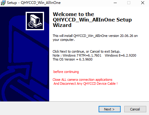
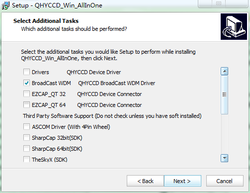
All-in-one Pack (Windows) is for all QHYCCD USB3.0 devices, including all Cooling CMOS cameras, QHY5III and QHY 5II series, QHYCFW3. We recommend you choose “Stable Version” as usual.
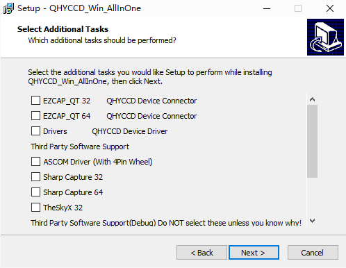
In this pack there are:
1. System driver. It must be installed to make devices work.
2. EZCAP_QT: it’s developed by QHYCCD which could be used in QHY devices tests, simple capture tasks, and above all, the management of updates. So even if you won’t use EZCAP_QT as your main capture software, we suggest you install it to get the latest information of QHY drivers/SDK updates.
3. Ascom driver: Ascom Platform is supported by most astronomy devices which connect to Windows.
4. SDK: SDK is the file of “.dll” format. With this the device can be identified in other capture software.
5. SkyX Plugin: special support for SkyX.
6. QHYCCD BroadCast WDM Driver: It is a broadcast driver that supports QHYCCD cameras with video broadcast function, which can meet the needs of customers to send video images to other target software.
How to install it?
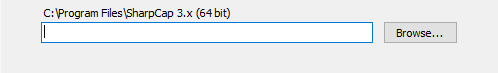
Take SharpCap (x64) for example:
Before the installation, make sure you’ve already installed SharpCap (X64) on your PC;
Then click ”Third Party Software Support” – “SharpCap 64”, the pack will detect the location of SharpCap files and install automatically; if not, please manually select root directory of SharpCap where you installed it, like: C:\Program Files\SharpCap 3.2 (64 bit)
Before using software, make sure you have connected the cooling camera to the 12V power supply and connected it to the computer with a USB3.0 data cable. If it’s a planetary/guiding camera, 12V power is not needed.
Note: We recommend 64-bit Software when you’re using cameras with a large sensor, such as QHY600. A full resolution image from the QHY600 is 120MBytes. It takes a significant amount of processing power and memory to capture, buffer, display and process. We therefore suggest using 64-bit software with the QHY600, for example, SharpCAP x64 , N.I.N.A x64. etc. Although the camera has 4GB of internal memory, 32-bit software will run within this memory area and the remaining memory may be not sufficient for normal operation.
EZCAP_QT is software developed by QHYCCD. This software has basic capture functions for QHYCCD deep sky cameras.
Run EZCAP_QT. Click “Connect” in Menu -> Camera. If the camera is successfully connected, the title line of EZCAP_QT will display the camera firmware version and the camera ID as shown below.
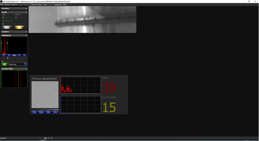
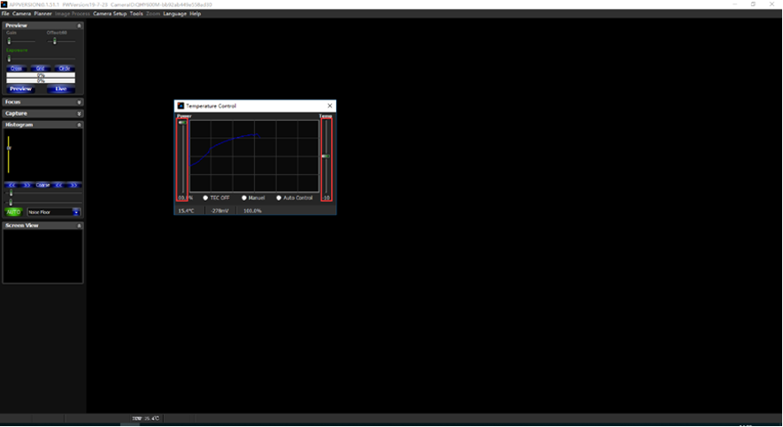
Click “Temperature Control” in “Camera Settings” to set the temperature of the CMOS sensor. You can turn on “Auto” to set the target temperature. For example, here we set the target temperature to -10C. The temperature of the CMOS sensor will drop quickly to this temperature (approximately 2-3 minutes). If you want to turn off cooling, you can choose Stop. If you just want to set the TEC power but not the temperature. You can select “Manual” and then set the percentage of the TEC power.
You can use the “preview tab” to preview and use the focus tool to focus. Then use the “capture tab” to capture the image.
Launch SharpCap. If the software and drivers mentioned above are installed successfully, the video image will appear automatically about 3 seconds after the software loads. You will also see the frame rate in the lower left corner of the software window as shown below.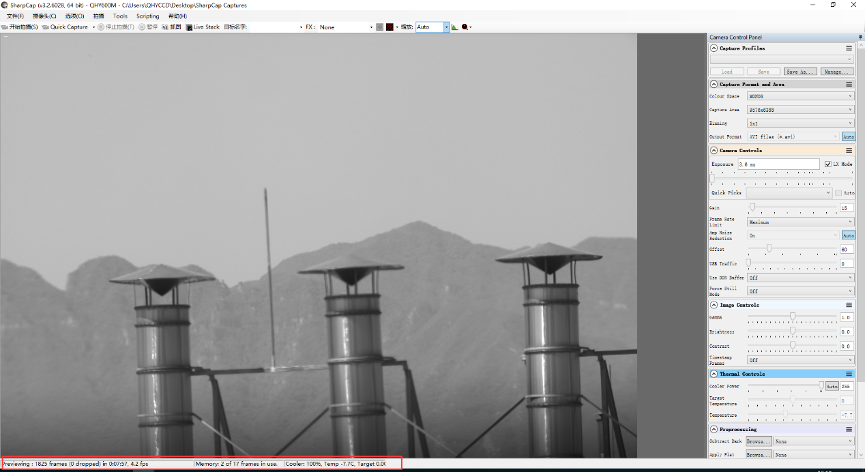
If you have already started the SharpCap software before connecting the camera, in order to open the camera, click on the “camera” in the menu bar and then select the device.
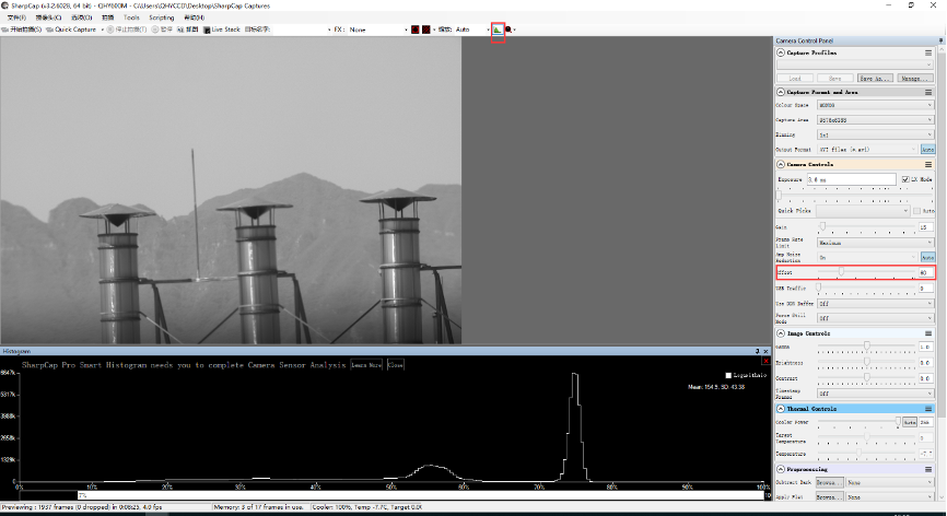
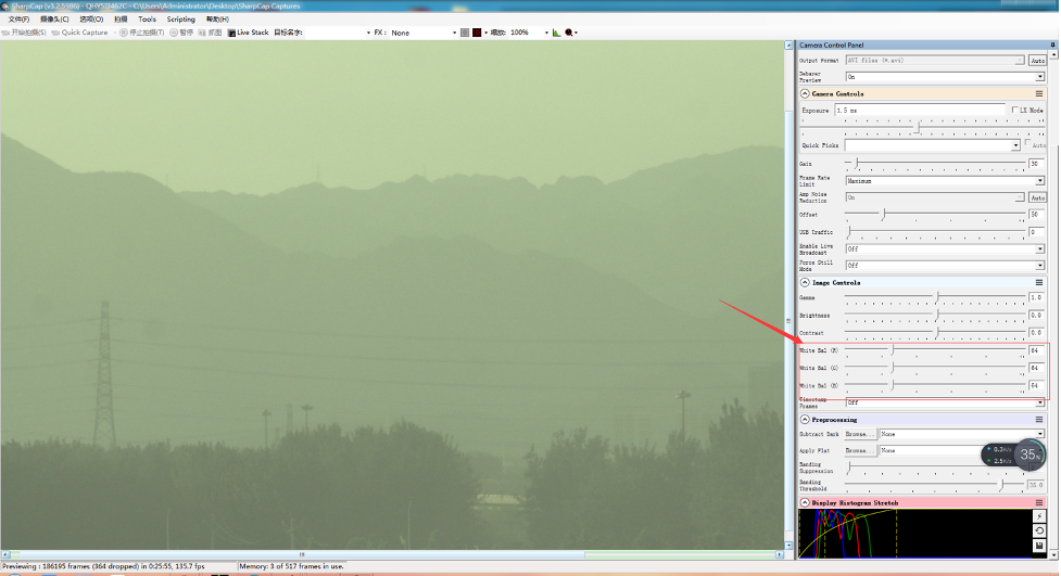
Offset adjustment. When you completely block the camera (i.e., like taking a dark frame) you may find that the image is not really zero. Sometimes this will reduce the quality of the image contrast. You can get a better dark field by adjusting the offset. You can confirm this by opening the histogram as indicated in the figure below.
If you want to enter the 16-bit image mode, select the “RAW16” mode.
By selecting the “LX” mode you can expand the exposure setting range and take long exposures.
After cooling devices connected to the 12V power supply, the temperature control circuit will be activated. You can control the CMOS temperature by adjusting the settings in the figure below. Basically, you can control the temperature of CMOS by either adjusting “Cooler Power” or clicking “Auto” and setting “Target Temperature”. You can also see the CMOS temperature at the lower-left corner of the software window.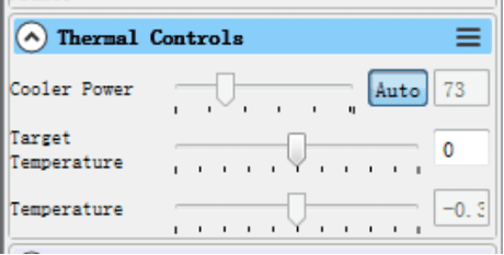
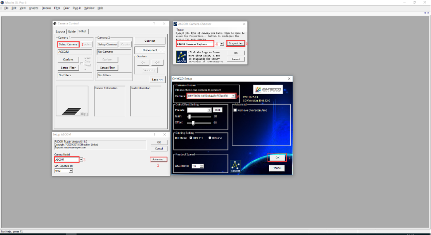
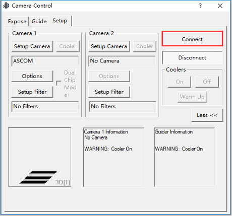
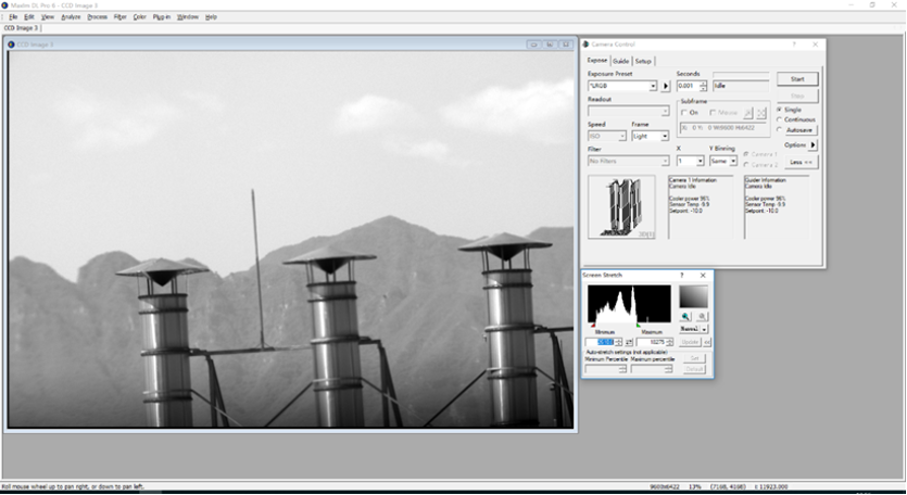
With ASCOM drivers, you can use the device with many software packages that support the ASCOM standard. We will use Maxim DL below as an example, but a similar procedure is used for The SkyX and other software packages supporting ASCOM.
First make sure you have not only loaded the ASCOM drivers but that you have also downloaded and installed the ASCOM platform from ASCOM. After both the drivers and platform are installed, start MAXIMDL. Follow the instructions shown below to finish the setup. Then Click Connect in and enter the software.

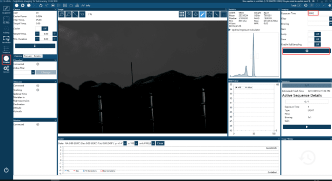
Open N.I.N.A. – Nighttime Imaging ‘N’ Astronomy. Drive connections via ASCOM.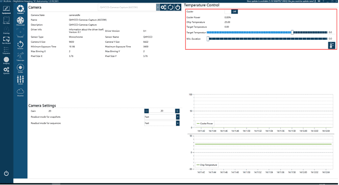
Turn on the TE cooler to set temperature. Then set the exposure time to capture the image.
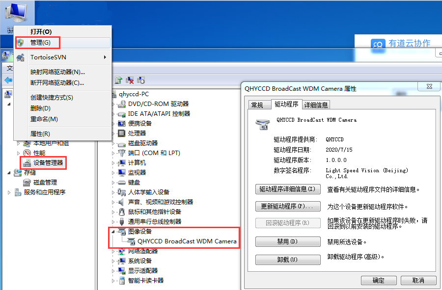
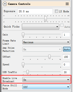
QHYCCD BroadCast WDM Camera is a broadcast driver that supports QHYCCD cameras with video broadcast function, which can meet the needs of customers to send video images to other target software. For example, use sharpcap to connect a WDM-enabled camera, and the sharpcap display video image can be sent to other WDM-supported software for display, which is suitable for video online broadcast applications.
The installation process is over, right-click the computer to find the device manager, and check that the image device name is QHYCCD BroadCast WDM Camera, which means the installation is successful.
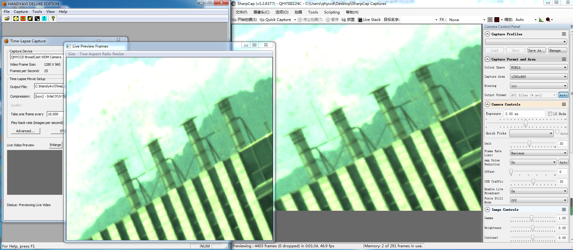
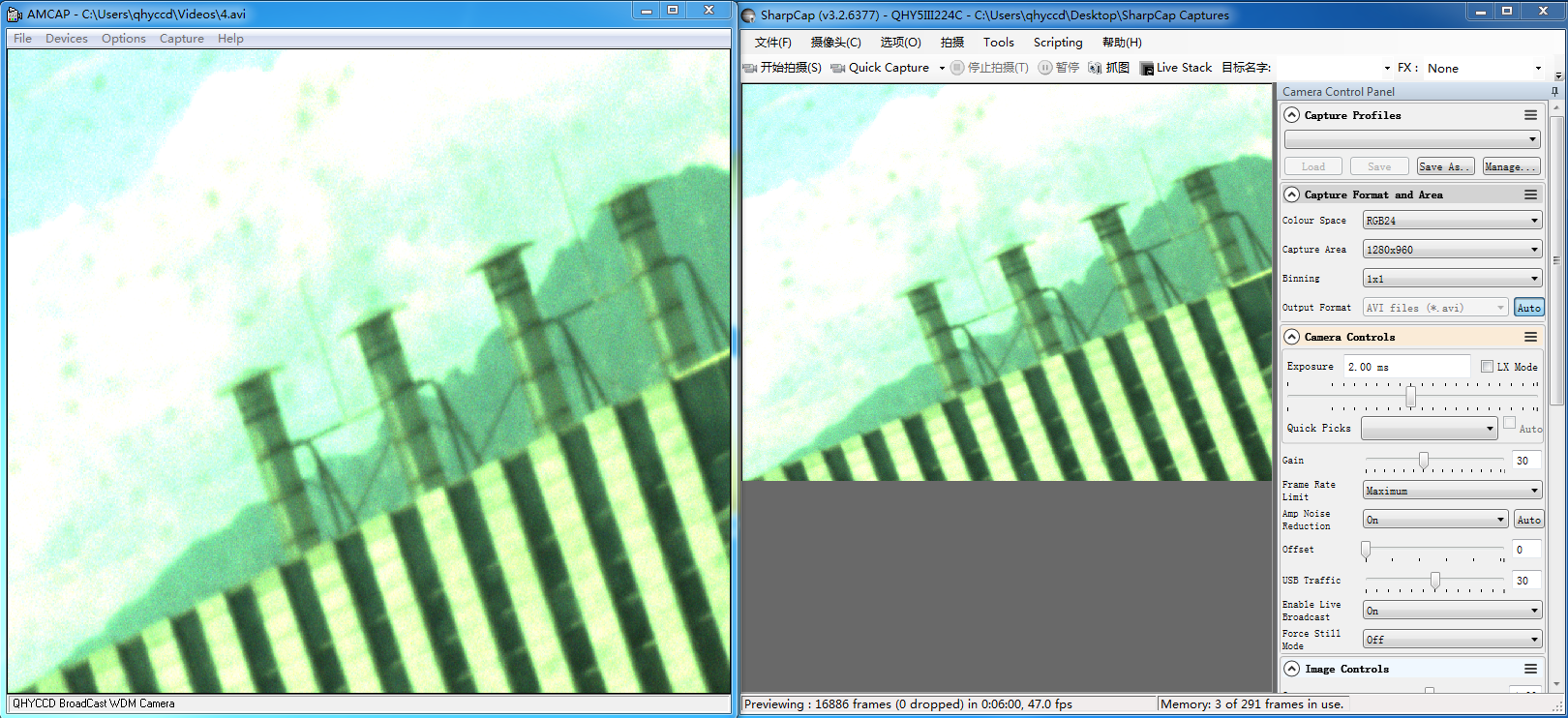 HANDYAVI test effect chart:
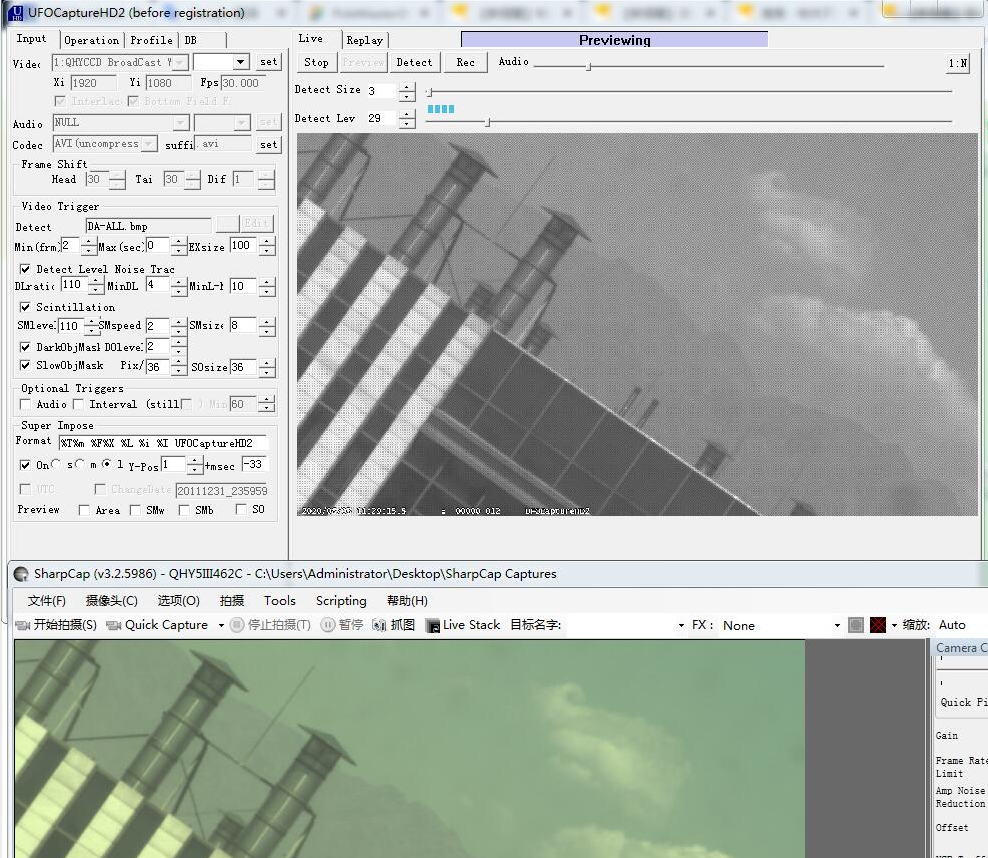
UFOCAPTURE test renderings:
Appendix: How to set Gain and Offset
Unity Gain of Some Models
| Model | Unit Gain |
| 600M/C | 25 (Extended Full Well Mode) * |
| 268M/C | 30 (Extended Full Well Mode) * |
| 294Pro | 1600 (11MP Mode)
2600 (47MP Mode) |
| 410C | 90 (Low gain)
40 (High gain) |
| 367C | 2800 |
| 247C | 2200 |
| 128C | 3300 |
| 168C | 10 |
| 183M/C | 10 |
| 163M/C | 120 |
| 174GPS | 17 |
| 550P | 85 |
*With the improvement of the CMOS technology, the 16bit CMOS camera has been released, like QHY600/268/411/461. For these cameras, even in lowest gain it has beyond the requirement of unit gain (less than 1e/ADU due to sufficient samples) So you can directly set gain0 as start. Please note QHY600/268C/411/461 has extend full well mode. In this mode you still need to find out the unit gain position.
For beginner, we recommend that you set the gain to “unit-gain”. Unit-gain is the gain when system gain is 1 (1e/ADU). This number is shown in the table above, like the unit-gain of QHY168C is 10. In fact, increasing or decreasing a bit doesn’t make a big difference.
You could increase or decrease Gain according to the condition. For example, if your optical system is fast, like F2.2 to F5, or long exposure for more than 5 minutes without narrowband filters, then you can decrease GAIN to achieve a higher dynamic range and make better use of full well capacity. By doing so you can avoid overexposure.
If you use narrowband filter on a slow optical system like F6 to F10, or short exposure time, the amount of photons received will be less. In this case you can increase GAIN to make better use of characteristics of low read-out noise in high GAIN value.
There is no fixed “best value” for OFFSET. To set OFFSET, you should take the bias frame and dark frame at a certain GAIN value, then check the histogram of the frames.
As you can see, the histogram distribution is a peak-like curve. By changing the OFFSET value, this curve will move left or right. We must guarantee the range of the whole curve is greater than 0, and it cannot be chopped off at the end. At the same time, we need to keep a bit of residue on the left side, just over 0 a bit. 100 to couple hundreds ADU are all okay. Don’t be too huge, however.
Pay attention that under different GAIN values, the width of this peak varies. The higher the GAIN is, the wider the distribution will be. So OFFSET value st low GAIN is not suitable for high GAIN, because the curve is very likely to be chopped off.
For those CMOS less than native 16-bits, the AD sampling accuracy doesn’t match perfectly with the full well capacity. At low GAIN level, the system gain will be couple electrons per ADU. The camera loses the ability to distinguish the strength of the signal because of such sampling error.
When GAIN increases, the system gain will decrease. However, increasing GAIN will limit the full charge of the well. If the system gain is 1 for a 12bit CMOS camera, the pixel will be saturated at only 4096 electrons (full well). Some bright stars will be easily saturated. This problem goes worse under fast optical system or long exposure. Over saturated objects cannot be fixed during post processing (unless you shrink stars, like in PixInsight). Also, the color saturation of the star will be affected. As result, the stars will be huge and white washed. We should decrease the gain value in this case, to gain a higher full well capacity.
Under long exposure or using fast optical system, the pixel will receive more photons. The variation of quantized noise from the photon which you can consider as natural dithering of the light intensity, will be greater than the “noise” from the sampling error. Therefore, the effect of the sampling error will diminish. By averaging multiple exposures, this will compensate the lack of depth of the picture because of the sampling error.
If the number of received photons is limited, like using narrowband filters or short exposures, we can increase the GAIN value. It is because the stars will not be easily saturated. At the same time, we limit the noise from the background cosmic radiation. Under this condition, the readout noise and quantized noise are the major factors that affect the ability to distinguish dim light or objects. By increasing the GAIN value in order to decrease the readout noise and quantized noise from sampling error, this would greatly increase the signal to noise ratio.
| Cooled CMOS Camera | Bayer |
| QHY600C | RGGB |
| QHY268C | RGGB |
| QHY410C | RGGB |
| QHY367Pro | RGGB |
| QHY128Pro | RGGB |
| QHY294C | RGGB |
| QHY247C | RGGB |
| QHY168C | RGGB |
| QHY165C | RGGB |
| QHY163C | GRBG |
| QHY183C | RGGB |
| QHY174C | RGGB |
| QHY178C | GBRG |
| QHY290C | GBRG |
| QHY224C | GBRG |
| Planetary and Guiding | Bayer |
| QHY5III174C | RGGB |
| QHY5III178C | GBRG |
| QHY5III224C | GBRG |
| QHY5III290C | GBRG |
| QHY5III462C | GBRG |
| QHY5III485C | RGGB |
| QHY5L-II-C | BGGR |
| QHY5P-II-C | GBRG |
| Cooled CCD Camera | Bayer |
| QHY8L-C | GBRG |
| QHY10-C | RGGB |
| QHY12-C | BGGR |
Now the ratio R”:G”=(R+bias)/(2R+bias) and it is not equ to 1:2. It shows the bias will effect the true value of the R:G. And the ratio of R:G will arious when the image light changed. It is hardly to correct with a fixed ratio.
But for DSO capture, You should keep the offset above zero and avoid the background is cut off. A background from 1000-5000 is a good value(16bit mode) for DSO imaging.
How to avoid the camera hanging?
If your camera hangs (stops downloading images and does not respond to commands) it may be caused by a number of things. Check the following:
1. In some computers with a VIA chipset and some types of motherboards, running the camera with SharpCap will not produce an image. But in ASCOM it works well. In this case, you need enable the DDR buffer of the camera.
2. Is there a leak for your mount or computer? If so, the leaking current may be transferred from computer to the camera via the GND. This may affect the USB transfer and cause data packet loss, hanging the camera. In this case you need to make sure that the computer and mount are well grounded.
3. Is the USB port voltage sufficient? The voltage of some computers’ USB ports is sometimes less than +5V. This may cause the camera to hang. In this case you can use a powered USB 3.0 HUB to connect camera, which will ensure that the camera gets +5V power.
4. Is your CPU utilization is too high? If your computer’s CPU utilization is too high, it will cause many frames to be lost and may cause the camera to hang. You can change the USB
traffic value to reduce the FPS and get more stable video transfer.
5. Is the USB cable connection is secure enough? Sometimes a connection issue with the USB cable to camera or USB cable to computer will cause some signal loss and may cause the camera to hang, particularly when you move the cables. In this case you can try to add a little silicon oil into the USB connector and socket. This can make the connection more stable.
6. Avoid the static electricity. Static electricity from the human body can cause the camera to hang. To ground yourself, touch the external metal case of the computer to discharge any static electricity before touching the camera.
7. Are you using the front USB port on your computer? The USB port on the front of some computers is not adequate for high-speed transfer because it is connected to mainboard by a cable which weakens the signal integrity. If you find that the camera always hangs when using the front USB port, try using a USB port on the rear panel of the computer instead. This will connect the camera to the chipset on the mainboard directly.
8. When the USB selective pause function is enabled in the system, it may cause the camera to hang during long hours of work. Follow the steps below to turn off this option. Windows power setting steps: 1. Click “Start button” and click “Settings”. 2. Click “Power and Sleep”, and click “Other Power Settings”. 3. Click “Change Power Plan”. 4. Click “Change advanced power settings”. 5. By default, the “USB Selective Suspend” function is enabled. (This may cause the image to freeze, the frame rate too become low, the video to become unsmooth, the image fail to refresh, and so on.) 6. Disable this function.
9. When you encounter a situation where the camera cannot output the usual frame rate after updating Sharpcap software, please download the All-In-One installation package and select the Sharpcap option during installation. The installation package will automatically update the QHY SDK in Sharpcap. Restart the sharpcap software after completion.
Image misalignment due to USB data transmission errors
What is happening here can be caused by USB communication problems or external interference problems. The data of the USB image packet being transmitted is wrong and cannot pass the CRC check, so the SDK judges it as a USB transmission error. The SDK will repair communication errors to avoid crashes, but this packet of data will also be lost. To trouble shoot this type of issue, note the following:
(1) Communication quality problems caused by USB cable damage or poor USB contact: The solution is to replace the USB cable, and check the connection of the USB cable to the computer and whether the connection between the USB cable and the camera is too loose.
(2) Some HUBs with mismatched signals may cause such problems. Connect directly or replace to another type of HUB. (It is recommended to use active HUB)
(3) The communication is experiencing interference problem caused by noise or voltage leakage of the AC adapter. Check whether the AC adapter of each device in the system is well grounded.
(4) You may be using an SDK and firmware that do not match. Download the latest installation package (QHY recently released the All-In-One installation package, which can automatically replace the SDK with one click, you only need to check the corresponding software in the installation package), or request QHYCCD technology Support remote assistance.
| Brand | QHYCCD |